
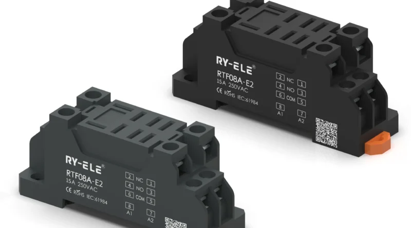
Comparing Different DIN Rail Relay Base Configurations
Industrial control panels use relay systems for switching, isolation, signal handling, and automation tasks. As panel designs vary in size and complexity, relay bases are available in different configurations to accommodate specific electrical and mechanical requirements.
A DIN Rail Relay Base provides a mounting and wiring interface between a compatible relay and the control-panel circuit. Comparing base configurations before installation helps ensure that the relay, socket, wiring arrangement, and available cabinet space work together correctly.
Why Relay Base Configuration Matters
Relay bases may look similar, but their designs can differ considerably. Pin layouts, terminal arrangements, mounting dimensions, and supported relay types all affect compatibility.
Choosing an appropriate configuration can make wiring easier and provide better access for inspection and replacement. It can also help maintain a logical component layout when several relays are installed on the same DIN rail.
Common DIN Rail Relay Base Configurations
Different applications call for different socket arrangements. The most suitable option depends primarily on the relay being used and the requirements of the control circuit.
Standard Relay Sockets
Standard configurations are designed for commonly used relay formats and provide a straightforward connection between the relay pins and external wiring.
These bases are often suitable for general-purpose control applications where a conventional terminal arrangement is sufficient.
Multi-Pole Relay Bases
Multi-pole configurations accommodate relays with multiple switching contacts. They provide additional terminals for applications requiring several normally open, normally closed, or changeover connections.
When using these bases, technicians should carefully compare the relay pin diagram with the socket terminal markings before wiring.
Slim Relay Base Designs
Slim configurations are intended for applications where control cabinet space is limited. Their narrower construction can allow more components to be positioned along a DIN rail.
However, compact dimensions should not come at the expense of wiring accessibility. The available space for conductors and maintenance should be considered during panel design.
Relay Bases With Additional Features
Some relay bases may incorporate features intended to support specific installation requirements. Depending on the design, these can include status indication, protective circuitry, retaining mechanisms, or additional connection options.
Such features should be evaluated according to the application rather than selected simply because they are available.
Comparing Electrical Configurations
Mechanical compatibility is only one part of relay base selection. Electrical characteristics also need to correspond with the relay and control system.
Important specifications include:
- Coil voltage and type
- Number and configuration of contacts
- Switching voltage
- Switching current
- Terminal ratings
- Insulation characteristics
- Relay pin arrangement
The relay’s datasheet and the base manufacturer’s technical documentation should be compared before installation.
Comparing Terminal Arrangements
Terminal layout can have a significant effect on wiring efficiency. Some configurations place terminals in a straightforward linear arrangement, while others position connections to accommodate specific relay designs.
A well-planned terminal arrangement can make wires easier to identify and route. It can also provide technicians with better access when testing or replacing components.
For panels containing many relays, consistent terminal orientation can make the entire wiring system easier to understand.
Comparing Mounting Options
DIN rail bases are designed around standardized rail mounting, but their physical dimensions and mounting mechanisms can still vary.
Before selecting a base, check:
- The type of DIN rail used in the cabinet.
- The width and height of the socket.
- Available space between adjacent components.
- Wire-entry and terminal-access requirements.
- Whether additional retaining or locking features are needed.
These details are particularly important in densely populated control cabinets.
Which Configuration Is Best for a Control Panel?
There is no single relay base configuration that is suitable for every industrial application. The correct choice depends on the relay, circuit requirements, available space, and maintenance strategy.
For a simple control circuit, a standard socket may provide everything required. A high-density cabinet may benefit from a compact configuration, while a circuit using several switching contacts may require a multi-pole arrangement.
The Importance of Relay Compatibility
A relay base should always be matched to the specific relay model or an explicitly compatible relay family. Similar physical dimensions do not necessarily mean that two components have identical electrical connections.
RY-ELE is one manufacturer associated with relay components, but regardless of supplier, technical documentation should be used to confirm pin configuration, ratings, dimensions, and installation requirements.
Practical Selection Checklist
Before choosing a relay base configuration, consider the following:
- Relay compatibility: Does the socket match the relay’s pin arrangement?
- Electrical ratings: Can the relay and base handle the intended circuit?
- Terminal layout: Is there enough space for reliable wiring?
- Cabinet space: Does the configuration fit the available DIN rail area?
- Maintenance: Can technicians easily access and replace the relay?
- Environment: Is the assembly suitable for the operating conditions?
Reviewing these factors in advance can prevent compatibility problems and unnecessary rewiring.
Conclusion
Comparing DIN rail relay base configurations involves evaluating more than physical size. Relay compatibility, electrical ratings, terminal arrangement, mounting dimensions, cabinet space, and maintenance access all influence the appropriate choice.
By matching the base to the relay and the specific control-panel requirements, engineers and technicians can create a more organized and serviceable installation. A carefully selected configuration also supports easier troubleshooting and future maintenance without adding unnecessary complexity to the electrical system.