What Are Shear And Bending Moment Diagrams?
Shear and Bending moment diagrams can sometimes not go hand-in-hand to solve. However, there are a few ways to overcome the problem. Solve for all the forces and moments on the outside, make a free-body diagram, and make a diagram of a shear. Starting from zero on the left of a set of axes, move rightwards, paying attention to the shear diagrams and moments on the free body diagram above. Free Body Diagram Now, we can begin drawing diagrams for the shear forces and the moments in flexing, starting at the left side of a beam.
Draw the shear force and bending moment diagrams for the beam with cantilevers supporting a 5lb centre load on the 3ft free end away from the wall. The free end is away from the wall. For example, we will define the shear force and bending moment diagrams for the simple brace beam carrying two loads. The first step to calculating these quantities and their spatial variations is to construct shear force and bending moment diagrams, (V(x)) and (M(x)), that are the shear forces and intrinsic bending moments that are generated by the beam, mapped over the length of the beam.
The shear diagrams will map out the internal shearing forces inside a beam or other bodies supporting a multi-force force perpendicular to the length of a beam. A shear force diagram is constructed by simply moving one segment down a beam from the origin to (say) the left and adding up the forces on the left side of the segment. Distributed loads are calculated by summing the product of the total forces (to the left of the section) and the distance (x) of the centroid of the distributed loads.
Distributed loads are slopes in a shear diagram, with each load at a point representing one hop on a shear diagram. Building upon our discussion of the bending moments, the shear forces represented by the shear force diagram also result from shear stresses acting on a given point of a structure. We will demonstrate in Unit 13 that they result from the shear and everyday stresses set in inner planes by bending loads.
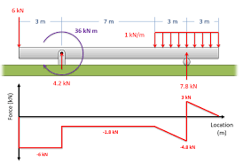
Below is a simple example of how the shear and moment diagrams look. After this, we will discuss the relationship between loads on a beam and the diagrams. Another application of the Shear and Bending Moment Diagrams is that deflections can easily be determined using the Moment Area Method or Conjugate Beam Method. Moment Diagrams A moment diagram will show internal curve moments in a horizontal beam subjected to different forces and moments perpendicular to the beam’s length.
Step 1 Draw the Free Body Diagram for a Beam To properly determine shear forces and the bending moments along the beam, we must know all the loads acting on it, including the external and the support’s reaction loads. The free body diagram for the crosswise-cut section of the beam in location (x) shows that there should be shear forces (V) and moments (M) over the cut section to keep the balance.


